-
Notifications
You must be signed in to change notification settings - Fork 3
New issue
Have a question about this project? Sign up for a free GitHub account to open an issue and contact its maintainers and the community.
By clicking “Sign up for GitHub”, you agree to our terms of service and privacy statement. We’ll occasionally send you account related emails.
Already on GitHub? Sign in to your account
tmp #1
Comments
|
(load "package://pr2eus/pr2-interface.l") (setq camera-frame "/head_mount_kinect_rgb_optical_frame") (defun compute-pan-angle (co-base) (setq node-state 'init) (defun handle-start (req) (defun handle-terminate (req) (ros::advertise-service "start_tracking" std_srvs::Empty #'handle-start) (defun tracking () (unix:sleep 2) |
|
#!/usr/bin/env python topic_name = "/ObjectDetection" def callback(msg): rospy.init_node('dummy_subscriber') |
|
catkin build roseus_mongo |
|
git clone https://github.com/HiroIshida/FA-I-sensor.git git clone https://github.com/HiroIshida/tbtop_square.git git clone https://github.com/HiroIshida/julia_active.git git clone https://github.com/HiroIshida/oven.git git clone https://github.com/HiroIshida/trajectory_tweak.git git clone jsk_pr2eus git clone jsk_roseus |
introduction to robot modelbefore startgin this tutorial, please do The The robot model As you can see, the state of 10 joints are shown as a |
introduction to robot modelbefore startgin this tutorial, please do get information of joint angles of a robotThe You must see: The robot model As you can see, the state of 10 joints are shown as a You get the list of 10 strings of joint name. The order of this list corresponds to the order of the float-vector you got by Now, let's set a custom angle vector to the robot model. Maybe, you want to set specific joint instead of set all the joints angle at once. For the The same thing can be done by solving inverse kinematicsUsually, in robotics, you want to guide the robot arm's end effector to a commanded pose (position and orientation). Thus, before sending an angle vector, you must know an angle vector with which the end effector will be the commanded pose. This can be done by solving inverse kinematics (if you are not familiar please google it). First, we create a coordinate (or a pose) (send fetch :rarm :inverse-kinematics |
introduction to robot modelbefore startgin this tutorial, please do get information of joint angles of a robotThe The robot model As you can see, the state of 10 joints are shown as a You get the list of 10 strings of joint name. The order of this list corresponds to the order of the float-vector you got by Now, let's set a custom angle vector to the robot model. Please click the IRT-viewer previously opend by Maybe, you want to set specific joint instead of set all the joints angle at once. For the The same thing can be done by solving inverse kinematicsUsually, in robotics, you want to guide the robot arm's end effector to a commanded pose (position and orientation). Thus, before sending an angle vector, you must know an angle vector with which the end effector will be the commanded pose. This can be done by solving inverse kinematics (if you are not familiar please google it). First, we create a coordinate (or a pose) (send fetch :rarm :inverse-kinematics |
|
|
|
The above function first solved IK inside to obtain the angle-vector such that the coordinate of the end-effector equals to Now you will see different solution is obtained from the previous one. |
|
I added quick tutorial using fetch. I try to design this tutorial to be minimum but enough to do something using real robot. Currently the tutorial includes (day1) basic usage for geometrical simulation only inside the euslisp and (day2) workflow to control real robot. I am planning to explain how to make simple tabletop demo in day3 (My DC2 submission is 5/8, so I will work on day3 part in the next week of the submission) You may wonder why I made this tutorial from scratch rather than taking advantage of pr2eus_tutorials and jsk_fetch_gazebo_demo, so I will explain the reason here. Actually, making a tutorial for pr2eus_tutorials was my first attempt. But simulating PR2 is too slow (2x slower than fetch), and even when I deleted camera and depth sensor stuff from the urdf file and launch it, it didn't make significant difference (of course, a little bit faster though). The bottleneck seems to be in the dynamical simulation and not in image (depth) rendering. Thus I can imagine that even if one use GPU the situation will not change so much. I think especially for students who cannot use real robot and do everything in the simulator, this slow simulation must be a nightmare. So I gave up on PR2. Then my second attempt was making step-by-step tutorial for jsk_fetch_gazebo_demo. It was a great demo but it is not minimum. In that demo, fetch starts from a location away from a desk, and because it use MCL to navigate, it takes really long time to reach the desk. (This is why I make this comment) I think manipulating object on table is good starting point. So, I am trying to make a tabletop demo. Unlike fetch_gazebo_demo, the robot is spawn just in front of the table and ready-to-start to grasp object. |
|
電子レンジのハンドル部分の隙間は狭く, 電子レンジの奥行方向の位置推定誤差があると, ドア開けタスクに失敗しやすくなります. 本実験では, この奥行方向の位置推定誤差にロバストな物体操作軌道を学習により獲得させようとしました. 奥行き方向の誤差のみを考えているのでFeasible regionの次元は1次元, つまりm=1です. まず初期軌道は, 人間の教示により与えました. その後100回の試行により学習させます. 学習後の軌道はこのようになりました. 電子レンジ底面にひっかけて, すべらせるような動きが獲得され, 直感的には, 奥行方向の位置誤差にロバストな軌道であるように見えます. 学習によりロバスト性が向上したことを定量的に示すために, 位置推定誤差をすこしずつずらして与え, その誤差のもとでもロボットがドア開けに成功するかを調べる実験を行いました. 青の点が成功を表しているので, 学習後には許容可能な誤差の領域が大幅に拡大していることがわかります. |
|
さらに, 近接センサによるフィードバックを用いた把持タスクにも提案手法を適用しました. この研究は, robomechへの論文提出後に行ったものですが, 紹介したいと思います. 左図のようにロボットハンドの先に2つの近接センサをつけます. そして, センサ値に応じて, グリッパの並進と回転を制御する問題を考えます. フィードバック則は12次元のパラメータでparameterizeされているとします. 今回は二次元の位置推定誤差を考慮しました. この動画は, 同様のタスクを人間である私が目を閉じて触覚フィードバックを用いてやってみた様子です. まず学習前の初期パラメータは私がハンドチューニングしました. ある位置推定誤差をいれてロボットがそれでも掴めるかどうかを, 学習前のパラメータを用いて行ったみたデモがこちらになります. このように近接フィードバックがうまくできていないため, 把持に失敗してしまっています. 学習のための試行は500回行いました. 次に, 全く同じだけの位置推定誤差をいれたあとに, 学習後のパラメータを用いて, つかめるかどうか試した様子が次のようになります. ひねりをきかして掴む動作により, 学習前では対応できなかった誤差に対応できるようになっていることがわかります. 電子レンジのドア開けタスクのときと同様に, すこしずつ推定誤差の値をずらして, それでも掴めるか否かを学習前, 学習後, それぞれのパラメータについて実験したものがこちらになります. 緑色の領域が学習前に成功した領域, 緑と青を足した領域が学習後に成功した領域です. 確かに, 学習後には許容可能な誤差の領域が拡大していることが確認できます. 一方, ハンドチューニングした初期パラメータの性能が良すぎたため, 学習による改善がわかりづらいのが, 本実験の残念なポイントです. |
|
基本的には次元が変わってもアルゴリズムは同じなので, 簡単のため1次元の誤差と, 1次元のパラメータのケースで説明します. この図の横軸がパラメータ, 縦軸が誤差を表しています. を考えていましたが, ここでは図示しやすくするため, 1次元の |
|
それぞれのサンプルは実際にロボットを用いた試行により得られます. 例えばこの失敗のラベルがついたk番目のサンプルですと, e_k=1.3に対応する認識誤差に基づいてtheta_k = -0.4に対応する物体操作軌道を, ロボットに実行させ, 失敗か成功かを判定することで得られます. ポスター前半でも紹介したように, 提案アルゴリズムの目的は, FRのサイズを最大化するような軌道パラメータを求めることでした. 今回のトイモデルですと, theta=0が最適値となります. 初期サンプルを与え, そこからアクティブサンプリングによりこの最適値を求めることを考えていきます. そして, アクティブサンプリングにより, これまで得られたデータから次に試行するパラメータと誤差の組を求め, それに対してロボットが試行をしてラベルを得るという流れを繰り返します. 最終的には真の最適パラメータの周囲にサンプルが収束します. 真の最適パラメータ意外にはサンプルが集中せず, 効率的なサンプリングが実現されています. テクニカルな話なので割愛しますが, 適応的にSVMのカーネル幅を更新していることも本アルゴリズムの押しポイントとなっています 最後にパラメータの最適値の推定値〜を得ます. これでアルゴリズムの目的が達成されました. |


introduction to robot model
before startgin this tutorial, please do
roscorein other terminal.get information of joint angles of a robot
The
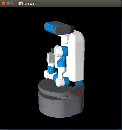
fetchfunction is create an instance named*fetch*which is a geometrical model of fetch-robot. Now you can view the model by calling the following function:The robot model
*fetch*contains the information of joints. The fetch robot has 10 joints, so let's look at state of these joints.As you can see, the state of 10 joints are shown as a
float-vector. Probably you need to know which value corresponds to which joints. To this end, the following method is useful.You get the list of 10 strings of joint name. The order of this list corresponds to the order of the float-vector you got by
:angle-vectormethod. By comparing those two, for example, you know thattorso_lift_jointhas angle of20.0.Now, let's set a custom angle vector to the robot model.
Please click the IRT-viewer previously opend by
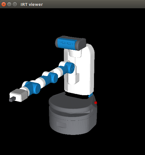
objectsfunction, then the you will see the robot model is updated.Maybe, you want to set specific joint instead of set all the joints angle at once. For the
shoulder_pan_jointcase for example, this can be done by:Note that the same thing can be done by
(setq *fetch* :shoulder_pan_joint :joint-angle 60), which is more common in jsk. You will get following image:solving inverse kinematics (IK)
Usually, in robotics, you want to guide the robot arm's end effector to a commanded pose (position and orientation). Thus, before sending an angle vector, you must know an angle vector with which the end effector will be the commanded pose. This can be done by solving inverse kinematics (IK) (if you are not familiar please google it). First, we create a coordinate (or a pose)
*co*byThen the following code will solver the IK:
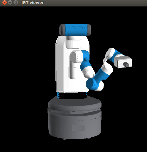
The above function first solved IK inside to obtain the angle-vector such that the coordinate of the end-effector equals to
*co*. Then set the obtained angle-vector to*fetch*. (I personally think this function is bit strange and conufsing. (For me it is more straightforward if the function return just sangle-vector without setting it*fetch*.) Note that you must care initial solution for IK. In the euslisp the angle-vector set to the robot is used as the initial solution. For example, in the above code I set it to " #f(0 0 0 0 0 0 0 0 0 0)" . In solving IK you can set some key arguments.:rotation-axis,check-collisionanduse-torosis particurally important. If:rotation-axisisnilthe IK is solved ignoreing orientation (rpy). If:check-collisionisnilthe collision between the links of robot is not considered. Please play with changing these arguments.Noting that iterative optimization takes place in solving IK, the solution will be change if you change the initial solution. Let's try with different initial solution:
Now you will see different solution is obtained from the previous one.
Now let's check that actually inverse kinematics is solved by displaying
*co*and the coordinate of end-effector*co-endeffector*.move-end-pos
The text was updated successfully, but these errors were encountered: