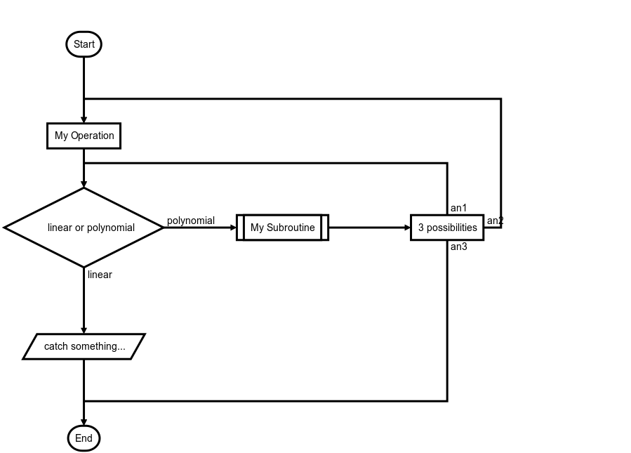
flowchart.js is a flowchart DSL and SVG render that runs in the browser and terminal.
Nodes and connections are defined separately so that nodes can be reused and connections can be quickly changed. Fine grain changes to node and connection style can also be made right in the DSL.
st=>start: Start:>http://www.google.com[blank]
e=>end:>http://www.google.com
getInfo=>input: Input Info
op1=>operation: My Operation
sub1=>subroutine: My Subroutine
cond=>condition: Yes
or No?:>http://www.google.com
io=>inputoutput: catch something...
printInfo=>output: Print info
para=>parallel: parallel tasks

st->getInfo->op1->cond
cond(yes)->io->printInfo->e
cond(no)->para
para(path1, bottom)->sub1(right)->op1
para(path2, top)->op1
See francoislaberge/diagrams on how to flowchart.js in the terminal.
flowchart.js is on CDNJS, feel free to use it.
You will also need Raphaël, which is also on CDNJS.
The demo html page is at example/index.html.
nodeName=>nodeType: nodeText[|flowstate][:>urlLink]
Items in [] are optional.
nodeName defines the nodes variable name within the flowchart document.
nodeType defines what type the node is. See Node Types for more information.
nodeText is the text that will be inserted into the node. Newlines are allowed and will be reflected in the rendered node text.
flowstate is optional and uses the | operator that specifies extra styling for the node.
urlLink is optional and uses the :> operator to specify the url to link to.
Defines the shape that the node will take.
Used as the first node where flows start from.
Default text is Start.
st=>start: start
Used as the last node where a flow ends.
Default text is End.
e=>end: end
Indicates that an operation needs to happen in the flow.
op1=>operation: operation
Indicates that IO happens in a flow.
io=>inputoutput: inputoutput
Indicates that Input happens in a flow.
getInfo=>input: Input info
Indicates that Output happens in a flow.
printInfo=>output: Print info
Indicates that a subroutine happens in the flow and that there should be another flowchart that documents this subroutine.
sub1=>subroutine: subroutine
Allows for a conditional or logical statement to direct the flow into one of two paths.
cond=>condition: condition
Yes or No?
Allows for multiple flows to happen simultaneously.
para=>parallel: parallel
Connections are defined in their own section below the node definitions.
The -> operator specifies a connection from one node to another like nodeVar1->nodeVar2->nodeVar3.
Not all nodes need to be specified in one string and can be separaged like so
nodeVar1->nodeVar2
nodeVar2->nodeVar3
Connection syntax is as follows:
<node variable name>[(<specification1>[, <specification2])]-><node variable name>[[(<specification1>[, <specification2])]-><node variable name>]
Items in [] are optional.
The following directions are available and define the direction the connection will leave the node from. If there are more than one specifiers, it is always the last. All nodes have a default direction making this an optional specification. <direction> will be used to indicate that one of the following should be used in its place.
- left
- right
- top
- bottom
Each node variables has optional specifiers, like direction, and some have special specifiers depending on the node type that are defined below. Specifiers are added after the variable name in () and separated with , like nodeVar(spec1, spec2).
Optional direction
startVar(<direction>)->nextNode
No specifications because connections only go to the end node and do not leave from it.
previousNode->endVar
Optional direction
operationVar(<direction>)->nextNode
Optional direction
inputoutputVar(<direction>)->nextNode
Optional direction
subroutineVar(<direction>)->nextNode
Required logical specification of yes or no
Optional direction
conditionalVar(yes, <direction>)->nextNode1
conditionalVar(no,  <direction>)->nextNode2
Required path specification of path1, path2, or path3
Optional direction
parallelVar(path1, <direction>)->nextNode1
parallelVar(path2, <direction>)->nextNode2
parallelVar(path3, <direction>)->nextNode3
A external link can be added to a node with the :> operator.
The st node is linked to http://www.google.com and will open a new tab because [blank] is at the end of the URL.
The e node is linked to http://www.yahoo.com and will cause the page to navigate to that page instead of opening a new tab.
st=>start: Start:>http://www.google.com[blank]
e=>end: End:>http://www.yahoo.com
Symbols that should possibly not be used in the text: => and -> and :> and | and @> and :$
If you want to emphasize a specific path in your flowchart, you can additionally define it like this:
st@>op1({"stroke":"Red"})@>cond({"stroke":"Red","stroke-width":6,"arrow-end":"classic-wide-long"})@>c2({"stroke":"Red"})@>op2({"stroke":"Red"})@>e({"stroke":"Red"})
st=>start: Start:>http://www.google.com[blank]
e=>end:>http://www.google.com
op1=>operation: My Operation
sub1=>subroutine: My Subroutine
cond=>condition: linear or polynomial :>http://www.google.com
io=>inputoutput: catch something...
para=>parallel: 3 possibilities

st->op1->cond
cond(true@linear)->io->e
cond(false@polynomial)->sub1(right)
sub1(right)->para
para(path1@an1, top)->cond
para(path2@an2, right)->op1
para(path3@an3, bottom)->e
via GitHub
Many thanks to js-sequence-diagrams which greatly inspired this project, and forms the basis for the syntax.


