-
Notifications
You must be signed in to change notification settings - Fork 0
[T ELEC 0] ODrive
We chose to use brushless motors that are cheap and powerful but it is difficult to control them. That's why we need an ODrive which is a high performance motor control. It can also control the encoders.
- We used the ODrive Version 3.5 48V. You can visit the official website for more information about the board ans its features.
- You will also need a Stm32 to communicate with the ODrive.
- And a CAN transceiver: the MCP2551.
The ODrive Tool is the accompanying PC program for the ODrive. It’s main purpose is to provide an interactive shell to control the device manually, as well as some supporting functions like firmware update.
We followed the instructions on the official ODrive documentation that you can find [here].(https://docs.odriverobotics.com/#downloading-and-installing-tools). Make sure that you follow the instructions correctly. The problem we encountered is that we had several python version installed. You need to only have the version specified.
We chose to use CAN to communicate with the ODrive. The stm32 will send orders to the ODrive to controll the motors.
As ODrive is in opensource, most of the features are developed by the community. We used a firmware that implemented a simple CAN protocol. You can find the project here.
Once you downloaded the project, you have to generate the .elf file to flash it on the ODrive. To do that, simply type make in the folder that contains the Makefile. We encountered several problems for this task, the main one is that we had to install tup and libfuse-dev. To install tup, you can check this tutorial.
And to make things easier we bought a ST-link to flash the firmware. Just connect it to the ODrive and the computer and follow the instructions of the official documentation.
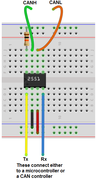
The circuit to build a CAN transceiver circuit using an MCP2551 chip is shown below. Connect the Tx and Rx pins to the ones corresponding to your stm32.

You can download the code that deals with the communication between the ODrive and the stm32. To understand this part of the code we'll explain a simple code that we used to send orders from our stm32. Take a code example from mbed here. You will need to sign up if you didn't.
The tricky part is the payload we send.
For example if you want to send the order:
char payload[4];
payload[0]=(uint32_t)100000;
payload[1]=(uint32_t)100000 >> 8;
payload[2]=(uint32_t)100000 >> 16;
payload[3]=(uint32_t)100000 >> 24;
The firmware version we used may not be the latest one since the project is still in development check the git on the references to download the latest version.
https://discourse.odriverobotics.com/t/can-interface-available-for-testing/1448 http://www.learningaboutelectronics.com/Articles/MCP2551-CAN-transceiver-circuit.php https://ide.mbed.com/compiler
- Home
- [History]
- [Tutorials]
- [TOOL]
- [MECA]
- [CODE]
- [ELEC]
- [MAKE]
- 3D Modeling
- Laser cutting
- 3D Printing
- CNC Extrusion
- [Tools 101]
- [Articles]
- [Type of motors]
- [Type of sensors]
- [Choice of microcontroller]
- [Eurobot 2019 Strategy]
- [Ressources]
- [Cloud]
- [Other Repositories]
- [Youtube Channels]
- [Miscellaneous]

