-
Notifications
You must be signed in to change notification settings - Fork 11
rotenc
This page is used to document my research and work on incremental rotary encorders. The idea is to add support for rotary encoders to M2tklib.
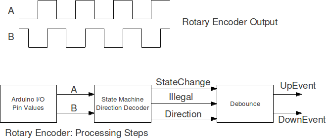
- An incremental rotary encoder has two outputs: A and B.
- The rotation with constant speed creates a wave form at output A and B.
- The wave forms are identical, except for a phase shift of 90 degree between A and B.
- The shift of the phase between A and B is used to detect the direction of the rotation (CW and CCW)

The picture above shows the steps for the processing of an incremental rotary encoder:
- Read A and B from the hardware.
- Derive direction
- Debounce and generate event
A state machine will derive the direction and some other information from the input signals A and B.
- Output Direction: 0 for CW and 1 for CCW
- Output Illegal or Unknown: 0 for valid direction, 1 for unknown state of the rotary encoder
- Output Asynchronous Event: This will reset the debounce and event generator block
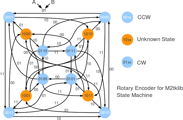
The state machine has the following structure:
- Outmost states (white on blue): CCW rotation
- Innermost states (black on blue): CW rotation
- Orange states: Unknown state of the rotary encoder
State encoding:
- Written inside of each state
- Bit 2: Direction
- Bit 3: Illegal/Unknown flag
- Bits 1 and 0: Logical level for A and B

The output values can be easily derived from the state code:
- Bit 2: Direction
- Bit 3; Valid (0) or not (1)
This is the next step function derived from the state machine. The code has pla syntax and could be processed by espresso or dgsop.
.i 6
.o 4
000000 0000
000001 0001
000010 0110
000011 1011

000100 0100
000101 0001
000110 1010
000111 0011

001000 0000
001001 1001
001010 0010
001011 0111

001100 1000
001101 0101
001110 0010
001111 0011


010000 0100
010001 0001
010010 0110
010011 1011

010100 0100
010101 0101
010110 1010
010111 0011

011000 0000
011001 1001
011010 0110
011011 0111

011100 1000
011101 0101
011110 0010
011111 0111


100000 1000
100001 0001
100010 0110
100011 1011

100100 0100
100101 1001
100110 1010
100111 0011

101000 0000
101001 1001
101010 1010
101011 0111

101100 1000
101101 0101
101110 0010
101111 1011
Minimzation does not provide a simple next step function. So I will implement a table based next step function:
- Lowest two bits of the state are take directly from the input.
- Leftmost bits (direction and unknown state) are read from a lookup table.
- The lookup table is compressed and has four states per byte.
uint8_t next_state_array[] = {
0x090, // 10 01 00 00
0x021, // 00 10 00 01
0x048, // 01 00 10 00
0x006, // 00 00 01 10

0x091, // 10 01 00 01
0x025, // 00 10 01 01
0x058, // 01 01 10 00
0x046, // 01 00 01 10

0x092, // 10 01 00 10
0x029, // 00 10 10 01
0x068, // 01 10 10 00
0x086, // 10 00 01 10
};

uint8_t next_state_fn(uint8_t state, uint8_t in)
{
  uint8_t new_state;
  new_state = next_state_array[state] >> ((in)*2);
  new_state &= 3;
  new_state <<= 2;
  new_state |= in;
  return new_state;
}
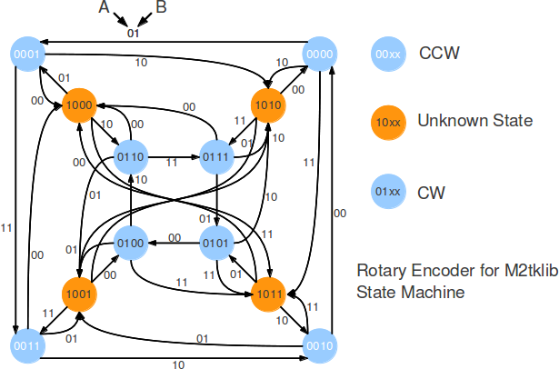
This is an update version of the state machine: If the direction changes, the machine will go through the unknown state. It makes the state machine more robust against spikes from the encoder.

This will lead to a different next state table:
uint8_t next_state_array_v2[] = {
0x0a0, // 10 10 00 00
0x02a, // 00 10 00 10
0x088, // 10 00 10 00
0x00a, // 00 00 10 10

0x099, // 10 01 10 01
0x0a5, // 10 10 01 01
0x05a, // 01 01 10 10
0x066, // 01 10 01 10

0x092, // 10 01 00 10
0x029, // 00 10 10 01
0x068, // 01 10 10 00
0x086, // 10 00 01 10
};
/*
  rotary encoder test pde

  Copyright (c) 2012, [email protected]
  All rights reserved.

  Redistribution and use in source and binary forms, with or without modification,
  are permitted provided that the following conditions are met:

  * Redistributions of source code must retain the above copyright notice, this list
    of conditions and the following disclaimer.

  * Redistributions in binary form must reproduce the above copyright notice, this
    list of conditions and the following disclaimer in the documentation and/or other
    materials provided with the distribution.

  THIS SOFTWARE IS PROVIDED BY THE COPYRIGHT HOLDERS AND
  CONTRIBUTORS "AS IS" AND ANY EXPRESS OR IMPLIED WARRANTIES,
  INCLUDING, BUT NOT LIMITED TO, THE IMPLIED WARRANTIES OF
  MERCHANTABILITY AND FITNESS FOR A PARTICULAR PURPOSE ARE
  DISCLAIMED. IN NO EVENT SHALL THE COPYRIGHT HOLDER OR
  CONTRIBUTORS BE LIABLE FOR ANY DIRECT, INDIRECT, INCIDENTAL,
  SPECIAL, EXEMPLARY, OR CONSEQUENTIAL DAMAGES (INCLUDING, BUT
  NOT LIMITED TO, PROCUREMENT OF SUBSTITUTE GOODS OR SERVICES;
  LOSS OF USE, DATA, OR PROFITS; OR BUSINESS INTERRUPTION) HOWEVER
  CAUSED AND ON ANY THEORY OF LIABILITY, WHETHER IN CONTRACT,
  STRICT LIABILITY, OR TORT (INCLUDING NEGLIGENCE OR OTHERWISE)
  ARISING IN ANY WAY OUT OF THE USE OF THIS SOFTWARE, EVEN IF
  ADVISED OF THE POSSIBILITY OF SUCH DAMAGE.


  prints values 0 1 2 3 for left rotation and 4 5 6 7 for right rotation on the serial monitor

  rotary encoder is connected to pins 8 and 9


*/


uint8_t next_state_array[] = {
0x0a0, // 10 10 00 00
0x02a, // 00 10 00 10
0x088, // 10 00 10 00
0x00a, // 00 00 10 10

0x099, // 10 01 10 01
0x0a5, // 10 10 01 01
0x05a, // 01 01 10 10
0x066, // 01 10 01 10

0x092, // 10 01 00 10
0x029, // 00 10 10 01
0x068, // 01 10 10 00
0x086, // 10 00 01 10
};

uint8_t get_input(void)
{
  uint8_t in = 0;
  if ( digitalRead(8) != 0 )
    in |= 1;
  if ( digitalRead(9) != 0 )
    in |= 2;
  return in;
}

/* based on the input, get the initial state */
uint8_t init_state(uint8_t in)
{
  return (in & 3) | 8;
}

/* based on the input, calculate the next state */
uint8_t next_state(uint8_t state, uint8_t in)
{
  uint8_t new_state;
  if ( state > 12 )
    state = init_state(in);
  new_state = next_state_array[state] >> ((in)*2);
  new_state &= 3;
  new_state <<= 2;
  new_state |= in;
  return new_state;
}

uint8_t rot_enc_state;
uint8_t rot_enc_debounce_cnt;
#define ROT_ENC_DEBOUNCE_VAL 2

uint8_t cnt = 0;

void prozess(void)
{
  uint8_t new_rot_enc_state;

  /* calculate the next state */
  new_rot_enc_state = next_state(rot_enc_state, get_input());

  if ( new_rot_enc_state != rot_enc_state )
  {
    /* if state has changed, then reset the debounce counter */
    rot_enc_debounce_cnt = 0;
    /* ... and store new state */
    rot_enc_state = new_rot_enc_state;

    delay(2);
  }
  else
  {
    /* only if the direction is known */
    if ( new_rot_enc_state < 8 )
    {
      /* increment the debounce counter */
      if ( rot_enc_debounce_cnt < ROT_ENC_DEBOUNCE_VAL )
      {
        rot_enc_debounce_cnt++;
        if ( rot_enc_debounce_cnt >= ROT_ENC_DEBOUNCE_VAL )
        {
          Serial.print(rot_enc_state);
          Serial.print(" ");
           cnt ++;
           if ( cnt >= 10 )
           {
            Serial.println("");
            cnt = 0;
           }
        }
      }
    }
  }

}


void setup()
{
  pinMode(8, INPUT_PULLUP);
  pinMode(9, INPUT_PULLUP);
  pinMode(13, OUTPUT);
  rot_enc_debounce_cnt = 0;
  rot_enc_state = init_state(get_input());

  Serial.begin(9600);
  while (!Serial) {
    ; // wait for serial port to connect. Needed for Leonardo only
  }
  Serial.println("Rotary Encoder");

}

void loop()
{
  prozess();
  if ( rot_enc_state < 8 )
  {
    if ( rot_enc_state & 4 )
      digitalWrite(13, LOW);
    else
      digitalWrite(13, HIGH);
  }
}
