-
-
Notifications
You must be signed in to change notification settings - Fork 77
FreeCAD BIM development news 04 June 2017
Hi all,
This is time for a new review of what has been going on in Arch development this month. Quite a lot actually, it's exciting that several things I've been working on during the last couple of months begin to flourish into pretty interesting and usable features.
There is another interesting thing happening, is a very good synergy between the WikiLab project I'm working on now, which you must grow tired of hearing about, and FreeCAD developement. FreeCAD fuels the project development, which in turns fuels FreeCAD with bugfixes and new features. Me and other FreeCAD community members are really keen to pursue and extend that synergy further with other projects.
As always, don't forget you can help me spending more time on FreeCAD, by sponsoring me via my Patreon campaign. As a side note, that campaign is really taking flight, sooner than I had expected, I'm highly overdue to update the campaign page, and add some whistles and bells such as goals and rewards.
As a possible reward, I am thinking about doing some short videos, explaining in detail specific feature of the Arch workbench, and more generally, doing BIM with FreeCAD. For example, one about walls, one about working with imported dwg files, things like that. These videos would be, in a first time, available to Patreon supporters only, as a kind of present to thank them, and then, after a couple of months, added on youtube for everybody. What do you think? Good idea? Lousy idea?
So enough of this, here is the real stuff:
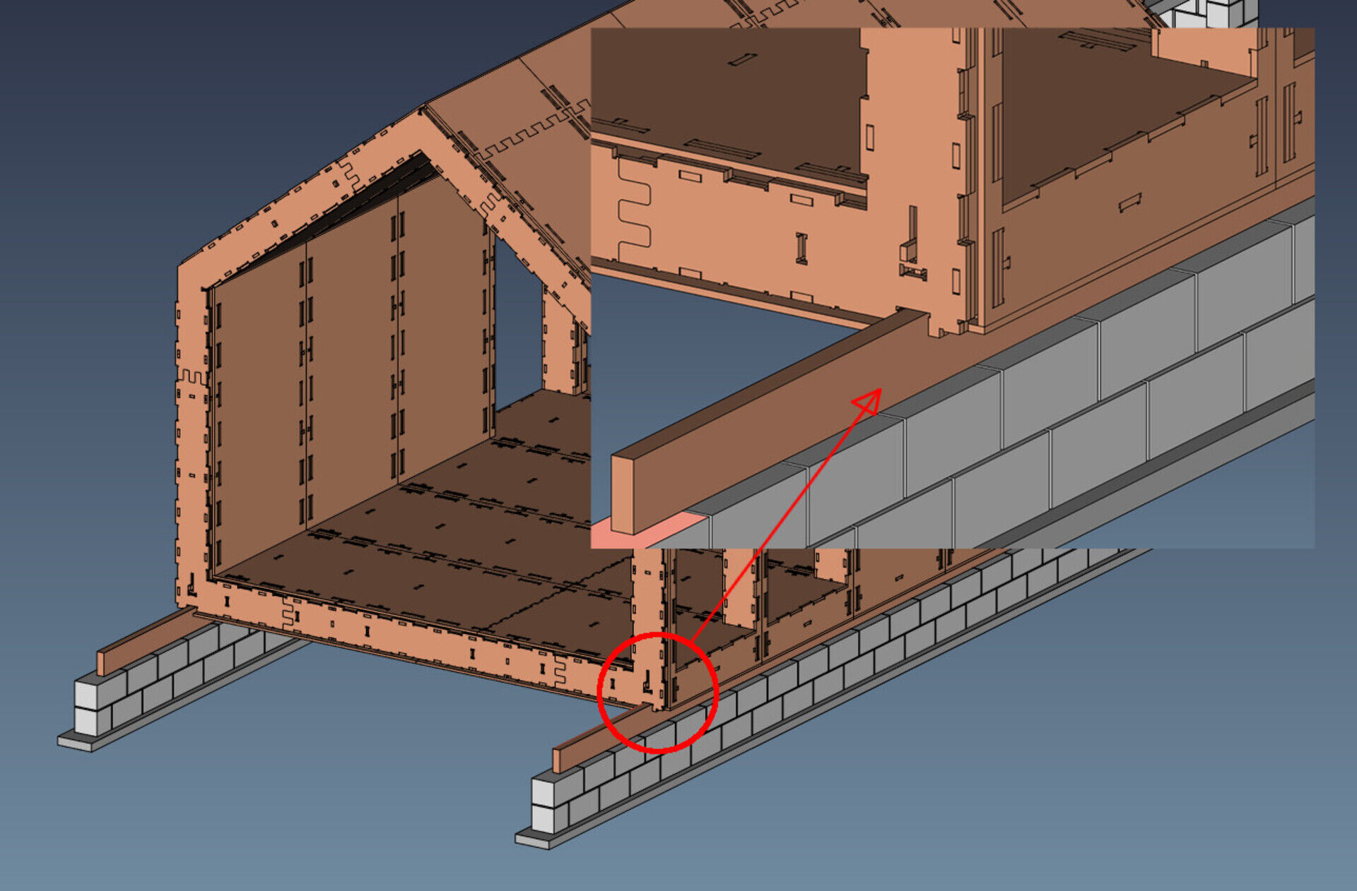
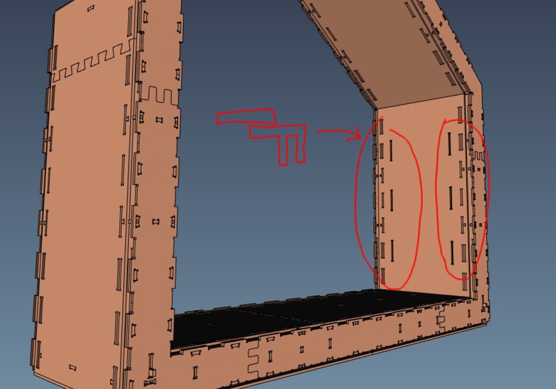
If you are following the progresses of our WikiLab project, you might have seen that the crowdfunding campaign ended successfully, and we are now getting started. The wood panels have been ordered already, the final cutting sheets are being made, and the cutting should begin next week. This will take roughly two months, during which we will contract a constructor to build the foundation and base walls, and hopefully everything will be ready to build the WikiHouse-based part, at the end of August, during the university holidays, and just before the rainy season.
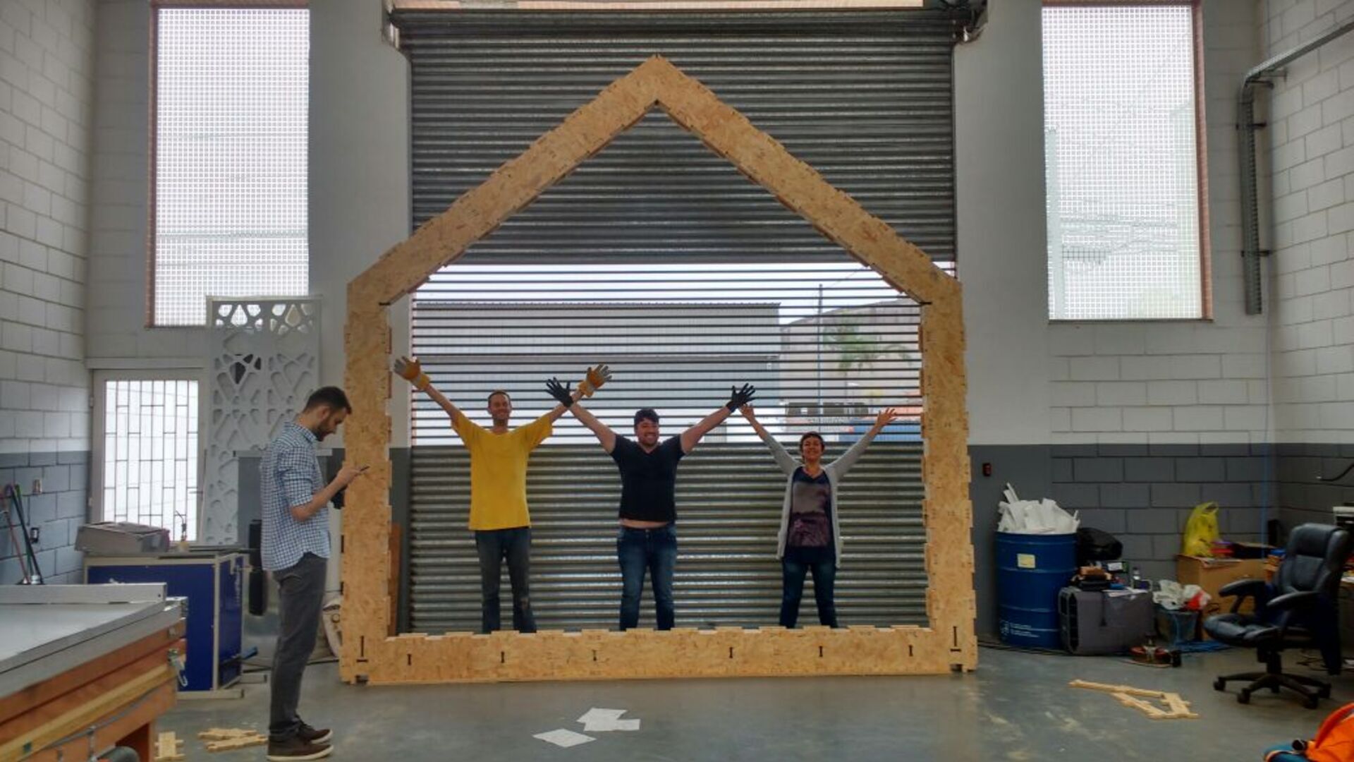
On the image above is a first "rib" we've been mounting this month, as a kind of proof-of-feasability, and to boost the crowdfunding campaign too. It went amazingly well, this element was built in about 2 hours by 5 people, it is very easy to understand and build, and the solidity is really impressive.
I'm also starting to write a manual (in portuguese) that willbe the actual construction document. No plans and sections in this project!
There are still several details to solve, some of them have been already discussed and solved on the WikiHouse community slack, which is a really cool way to solve these issues collaboratively, something we've been doing with OpeningDesign for quite some time already ;)
Last month I also had an online conversation with Harry Knight from the WikiHouse Foundation, and wrote an article on Medium.com about our project. Check it up!
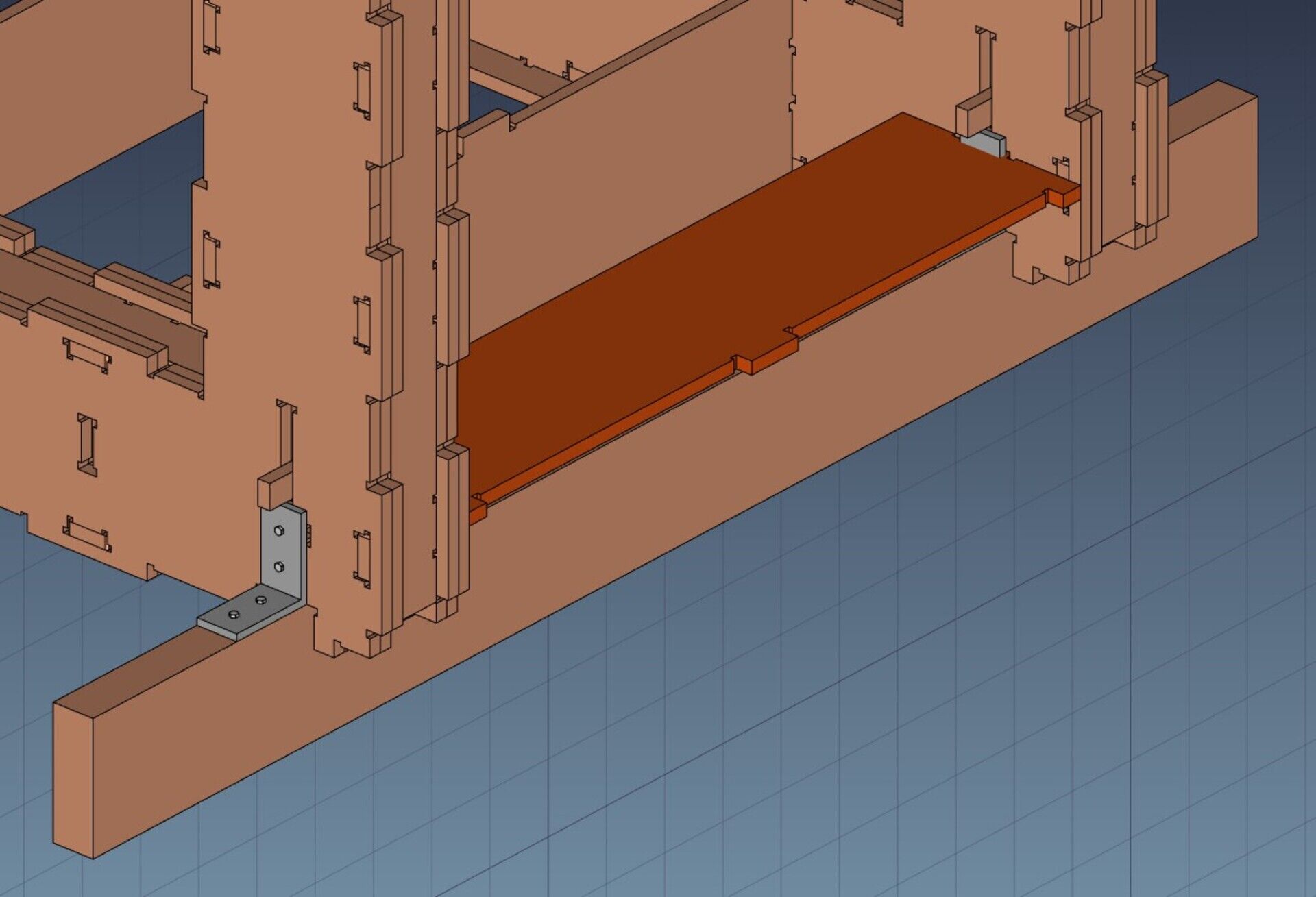
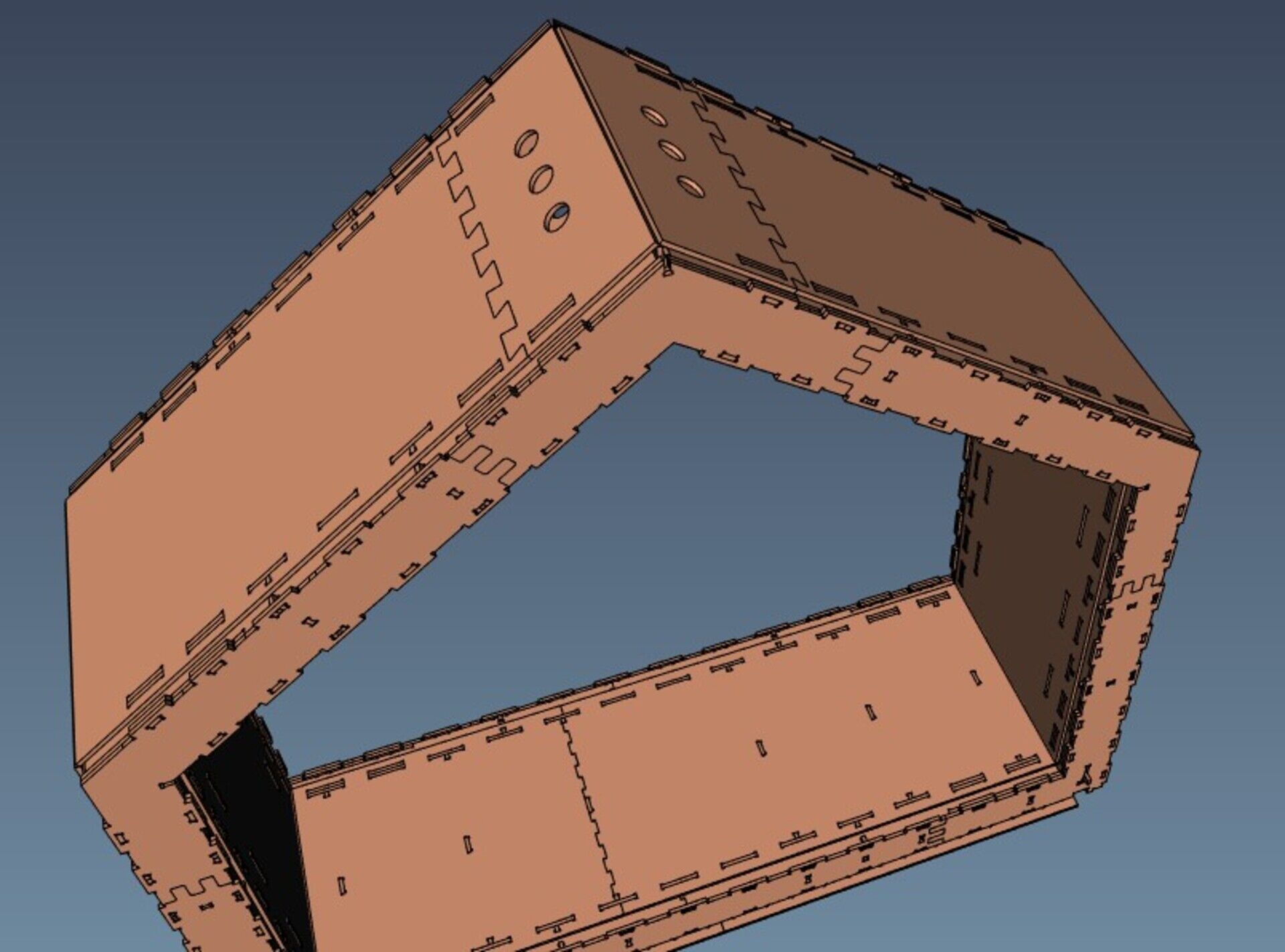
We are also studying small changes and improvements to the design, such as holders for shelf supports, and ventilation holes at the top, that can be closed with 3D-printed custom lids.
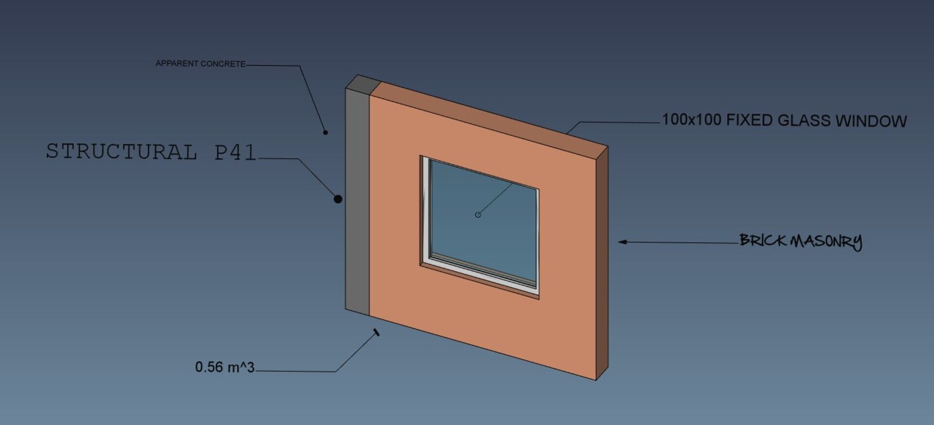
This is a new feature I've been working on, inspired by Revit's tag objects. In Revit, you have different types of tags, that you can attach to an existing object. That tag will then automatically display a certain information about the attached object. For example, material tags will show the material of the object, door tags will show the door number, etc.
In FreeCAD I decided to go for a bit more generic approach: There is a new generic Draft Label object, which is made of a piece of text and a two-segment line, which can have an arrow at its end. The text can be made to display some property from the attached object. At the moment only a small list of properties are available, and can be selected from a drop-down box, but the system is very extensible and you could have those Labels display just any kind of information that can be retrieved from the base object.
As always, this is only the first, rough version, it works, but over time and use it will certainly refine ito something more solid and powerful. It should also gain additional feature so it can be used for all the Revit scenarios: show component numbers, space tags, etc. All these should be displayable in a distinct manner (in a rounded rectangular frame, in a circle, etc...)
The other big news of this month, is that I've been elected for a Shuttleworth Foundation Flash Grant! Thanks to OpenSourceEcology fellows, who indicated me! I still don't have fully formed plans for what to do with the money, but a couple of things I definitely want to do: 1) Help founding the wikilab project above (that is done already), 2) Turn the FreeCAD manual into a printed book. Most of the work is done already, it still needs a professional editor review, then it can be printed and sold, which nowadays is very easy thanks to sites like lulu.com. And 3) extend what I'm doing with the money from my Patreon campaign, spend more time coding for FreeCAD. I would be able to work half-time on FreeCAD for a coupe of months, I'm trying to see how to set that up now. As a point 4), I might have more/better ideas later on, still thinking about it.
This year, FreeCAD has received four student projects for the Google Summer of Code. For who doesn't know, it is a program by Google to sponsor students to work on open-source projects during the (northern hemisphere) summer months. We are now approximately at the middle of the coding period, and our 4 students are doing great!
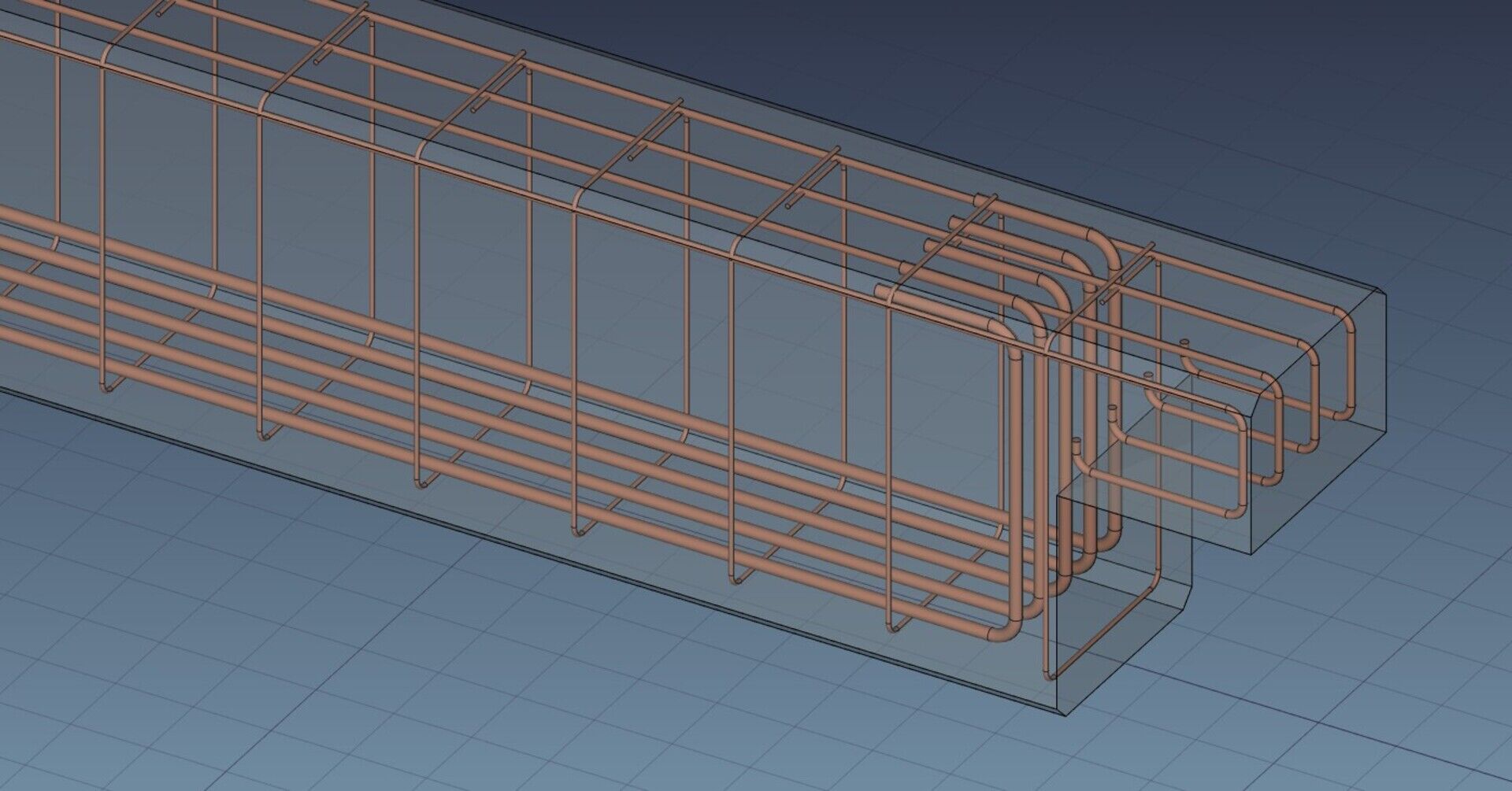
I am myself mentoring one of these projects, together with Bernd, which is Amritpal Singh's proposal to extend the Reinforcement bar tools in FreeCAD's Arch module. So far so (very) good, Amritpal is surprising us with the quality of his code, which you can already test if using a development version of FreeCAD: Just install the Reinforcement addon via the addons manager, and on next run, the Arch workbench will detect it and add its tools under its current Rebar tool.
The objective of Amritpal's work is to extend the User Interface around the Rebar tool, to add it a series of tailored dialogs to create specific types of reinforcement bars, such as straight bars, U-shaped bars, stirrups, etc. All this UI work integrates with the current Rebar object, which is kept as the overall, can-do-everything Rebar object. The different dialogs help the user to create and edit these rebars in a more friendly way, but doesn't remove anything of the power of the base rebar object, which is simply made of a profile, an extrusion path, and a series of placements, and can therefore represent any kind of rebar we can think of.
Everybody wins with this approach: The normal user, who just wants a clear and easy way to add reinforcement bars, and the power user, for who these dialogs are not enough and who wants to tweak or script these rebars in any way possible.
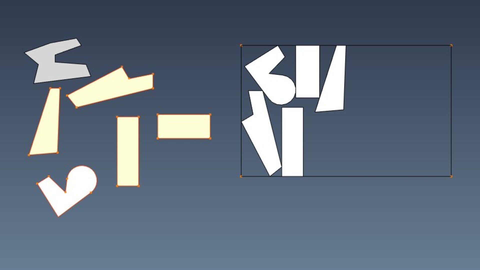
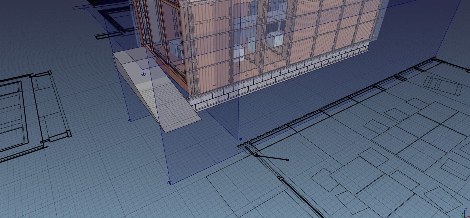
Here is the best part, in my opinion. I'm working (it's not finished yet, but working already) on an algorithm to perform bin packing in FreeCAD. It is an operation that consists in placing/packing different shapes inside a container (the bin), so it uses as little space as possible. The immediate output, obviously, is toproduce cut sheets for WikiHouse-style constructions, like this:

Interestingly, this is a subject that renders a lot of theory (lots of research papers on the net), but few open-source applications. The only "readable" ones I found were SVGNest and the WikiHouse plugin for SketchUp. None of them is usable directly in FreeCAD (different coding language, too tied into their host system, etc), but they provided precious resource to understand how such an algorithm should work.
They both use the same concept, which is the no-fit polygon. The idea is more or less this: You place a first piece inside the container. Then, for each other piece, you try to "rotate" it around the already placed piece(s). You are basically trying to place the new piece as close as possible to the ones already there. By doing this, you end up defining a "no-go" zone, that is, a zone where our piece cannot go otherwise it would overlap the already placed pieces. By subtracting that zone from the container area, you obtain an "available zone" where the new piece can be placed. You then place the piece at the leftmost available position in that zone, try again with different rotations of the piece, measure the results, and keep the one that occupies the smallest space.
The above concept is working already. It takes a lot of time now, it still needs a lot of optimization. But the concept seems solid. Later on, I will try to implement a genetic algorithm which would run several passes, swapping the order of some pieces, and keeping the best solution. There is a lot of space for improvements.
In the coming days/weeks I should have a basic implementation ready in FreeCAD, so we can start playing!
The nesting system described above is made to work with any shape or feature of FreeCAD. You select a series of flat objects, and another flat object as the container, and the algorithm will return a series of placement transformations, that you can apply to the object to have them packed into the space defined by the container shape. So this will work with any Part-based object.
However, the main interest for me is to use this with Arch Panel objects, for constructions such as our WikiHouse-based project above. These panels, at the moment, already have several features that will be useful for this kind of use, such as the Panel Cut feature that produces a flat view of a Panel, to be placed on a Panel sheet, you see that everything is ready for the nesting, we already have both the shapes and the container.
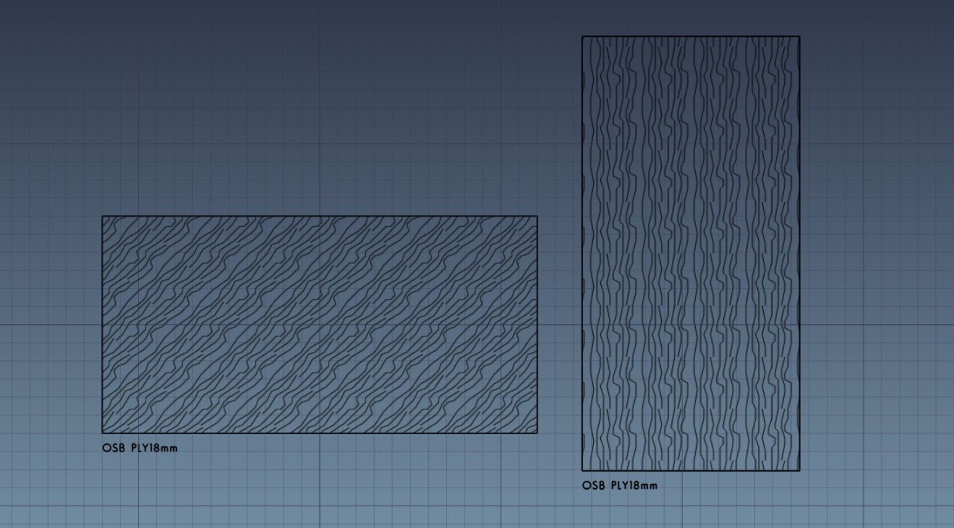
I already added a couple of useful features such as individual margin settings for each Panel Cut (the minimal distance it must keep with other pieces on the sheet), and the ability to render a Panel Cut either as a Wire or a Face. I also added a way to define and represent wood fiber orientation on a Panel Sheet:
This, allied with a way to restrict possible orientations of a piece on the sheet, will allow to have the nesting algorithm respect the fiber orientation when placing the pieces. There are also other features to come, such as the possibility to use any shape as the container (at the moment it is restricted to rectangular shapes), and I believe we will have a pretty powerful and flexible system.
Then the last operation needed in order to make FreeCAD produce WikiHouse components entirely, is to generate Path objects from the Panel Sheets, a task that has been already worked on extensively by Sliptonic (check this video where he explains it all).
That's it for this month I guess, as always,all comments and ideas are welcome, be it by posting on Patreon, on my blog, or on the FreeCAD forum!

